Procedure for Concrete Compression Test

Test process for Compression Test
The compression test shows the best possible strength concrete can achieve in perfect conditions. The compression test measures concrete strength in the hardened state. Field concrete samples are prepared, cured and tested according to ASTM standard procedures. Specimens are prepared from concrete taken from different construction sites. Following processes and calculations are used for measuring compressive strength of cylindrical concrete specimens.
Standard Test Method for Compressive Strength of Cylindrical Concrete Specimens (ASTM Designation: A 370 – 03)
This test method consists of applying a compressive axial load to cylinders at a rate which is within the prescribed range until failure occurs. The compressive strength of the specimen is calculated by dividing the maximum load attained during the test with the cross-sectional area of the specimen. This strength is commonly specified as a characteristic strength of concrete measured at 28 days after mixing.
Making and Curing Concrete Test Specimens
Following operations are executed in order to assure that test specimens are in accordance with the standard prior to testing.
Molds
Molds used for preparing samples are in agreement with the standard if the following conditions satisfy:
- Molds shall hold their dimensions and shape under all conditions of use.
- A suitable sealant, such as heavy grease, shall be used where necessary to prevent leakage through the joints.
- Positive means shall be provided to hold base plates firmly to the molds.
- Reusable molds shall be lightly coated with oil before use.
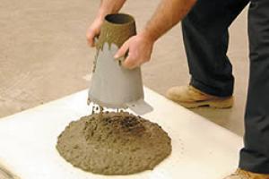
Sampling
The first step is to take a test sample from the large batch of concrete. This should be done as soon as the discharge of the concrete commences. The sample should be representative of the concrete supplied.
Tamping Rods
Tamping rods are used to distribute the concrete evenly prior to the start of consolidation. Two sizes are specified in ASTM methods. Each size shall be round, straight steel rod with at least the tamping end rounded to a hemispherical tip of the same diameter as the rod. Larger rod, 6/8 in. (16 mm) in diameter and approximately 24 in. (600 mm) long can be used for tamping.
Test Procedure
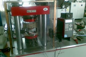
 Placing the Specimen — The plain (lower) bearing block is placed, with its hardened face up, on the table of the testing machine directly under the spherically seated (upper) bearing block. The bearing faces of the upper and lower bearing blocks are cleaned and the test specimen is placed on the lower bearing block.
- Zero Verification and Block Seating— prior to testing the specimen, it is verified that the load indicator is set to zero. If the indicator is not properly set to zero, it is adjusted.
- Rate of Loading— the load is applied continuously and without shock.
- Standards specify that for testing machines of the screw type, the moving head shall travel at a rate of approximately 0.05in. (1mm)/min when the machine is running idle. While for hydraulically operated machines, the load shall be applied at a rate of movement (platen to crosshead measurement) corresponding to a loading rate on the specimen within the range of 20 to 50 psi/sec (0.15 to 0.35 MPa/sec).
- During the application of the first half of the anticipated loading phase, a higher rate of loading is allowed.
- No adjustment is made in the rate of movement of the platen at any time while a specimen is yielding rapidly immediately before failure.
- Load is applied until the specimen fails, and the maximum load carried by the specimen during the test is recorded. The type of failure and the appearance of the concrete are also noted.
Calculations
 Compressive strength of the specimen is calculated by dividing the maximum load carried by the specimen during the test with the average cross-sectional area. Determine and express the result to the nearest 10 psi (0.1 MPa).
Data Logger
A data logger or data recorder is an electronic device that records data over time or in relation to location either with a built in instrument or sensor or via external instruments and sensors. Increasingly, but not entirely, they are based on a digital processor (or computer). They are generally small, battery powered, portable, and equipped with a microprocessor, internal memory for data storage, and sensors.
Acquirement of Data from the Data Logger
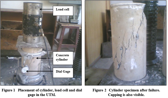
The displacement transducers or strain gage-based transducers are connected with a state of the art data acquisition system called “Data Logger” (Data logger Kyowa UCAM-70A with strain gage-based transducers attached through Transducers cables). The displacement transducers are connected to the data logger through transducer cable and measurement could be made afterwards. A dial gage is connected with the concrete cylinder to record displacement and a steel plate of flat surface is placed on the cylinder for the uniform distribution of load. The load cell is placed over the steel plate. Load is applied by the universal testing machine till failure of the sample. The load vs. displacement data recorded in the data logger is transferred to computer and then analyzed. Stress-strain curves for the concrete cylinders are drawn after the data analysis.
Making and Curing Concrete Test Specimens
Following operations are executed in order to assure that test specimens are in accordance with the standard prior to testing.
Molds
Molds used for preparing samples are in agreement with the standard if the following conditions satisfy:
- Molds shall hold their dimensions and shape under all conditions of use.
- A suitable sealant, such as heavy grease, shall be used where necessary to prevent leakage through the joints.
- Positive means shall be provided to hold base plates firmly to the molds.
- Reusable molds shall be lightly coated with oil before use.
Sampling
The first step is to take a test sample from the large batch of concrete. This should be done as soon as the discharge of the concrete commences. The sample should be representative of the concrete supplied.
Tamping Rods
Tamping rods are used to distribute the concrete evenly prior to the start of consolidation. Two sizes are specified in ASTM methods. Each size shall be round, straight steel rod with at least the tamping end rounded to a hemispherical tip of the same diameter as the rod. Larger rod, 6/8 in. (16 mm) in diameter and approximately 24 in. (600 mm) long can be used for tamping.
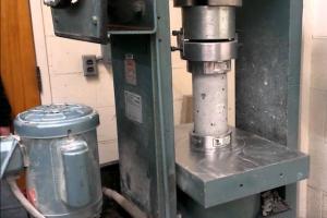
Test Procedure
- Placing the Specimen — The plain (lower) bearing block is placed, with its hardened face up, on the table of the testing machine directly under the spherically seated (upper) bearing block. The bearing faces of the upper and lower bearing blocks are cleaned and the test specimen is placed on the lower bearing block.
- Zero Verification and Block Seating— prior to testing the specimen, it is verified that the load indicator is set to zero. If the indicator is not properly set to zero, it is adjusted.
- Rate of Loading— the load is applied continuously and without shock.
- Standards specify that for testing machines of the screw type, the moving head shall travel at a rate of approximately 0.05in. (1mm)/min when the machine is running idle. While for hydraulically operated machines, the load shall be applied at a rate of movement (platen to crosshead measurement) corresponding to a loading rate on the specimen within the range of 20 to 50 psi/sec (0.15 to 0.35 MPa/sec).
- During the application of the first half of the anticipated loading phase, a higher rate of loading is allowed.
- No adjustment is made in the rate of movement of the platen at any time while a specimen is yielding rapidly immediately before failure.
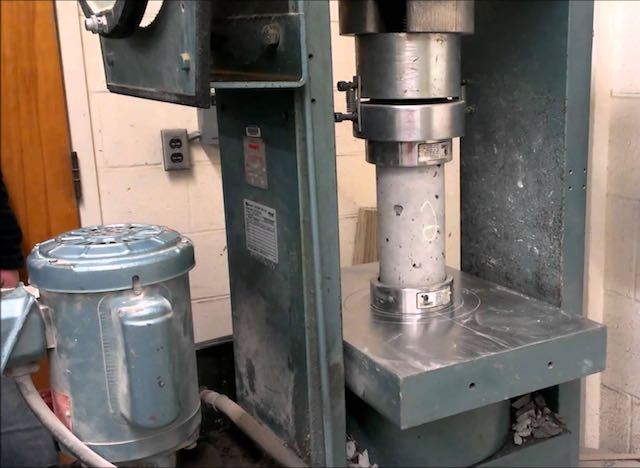
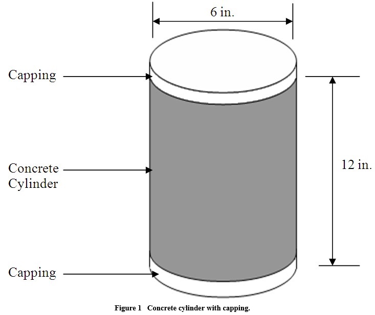
- Load is applied until the specimen fails, and the maximum load carried by the specimen during the test is recorded. The type of failure and the appearance of the concrete are also noted. concrete-cylinder-capping.jpg
Calculations
Compressive strength of the specimen is calculated by dividing the maximum load carried by the specimen during the test with the average cross-sectional area. Determine and express the result to the nearest 10 psi (0.1 MPa).
Data Logger
A data logger or data recorder is an electronic device that records data over time or in relation to location either with a built in instrument or sensor or via external instruments and sensors. Increasingly, but not entirely, they are based on a digital processor (or computer). They are generally small, battery powered, portable, and equipped with a microprocessor, internal memory for data storage, and sensors.
Acquirement of Data from the Data Logger
The displacement transducers or strain gage-based transducers are connected with a state of the art data acquisition system called “Data Logger” (Data logger Kyowa UCAM-70A with strain gage-based transducers attached through Transducers cables). The displacement transducers are connected to the data logger through transducer cable and measurement could be made afterwards. A dial gage is connected with the concrete cylinder to record displacement and a steel plate of flat surface is placed on the cylinder for the uniform distribution of load. The load cell is placed over the steel plate. Load is applied by the universal testing machine till failure of the sample. The load vs. displacement data recorded in the data logger is transferred to computer and then analyzed. Stress-strain curves for the concrete cylinders are drawn after the data analysis.