To Calibrate a Pressure Gauge Using a Dead Weight Pressure Gauge Calibrator

Apparatus
- Dead weight pressure gauge calibrator having the following main components,
- Cylinder
- Weights
- Leveling screws
- Spirit level
- Cylinder inlet
- A gauge to be calibrated
- Hydraulic bench
Concepts:
Calibration of guage:
To compare the values of an instrument with that of the standard ones is known as calibration of that instrument.
Pressure gauges:
The instruments with the help of which we measure the pressure are called as the pressure gauges.
![]() Also Read: Calibration of Rectangular Notch | Other Fluid Mechanics Experiments
Also Read: Calibration of Rectangular Notch | Other Fluid Mechanics Experiments
Absolute Pressure:
The pressure measured with reference to absolute zero is called as absolute pressure.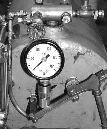
Gauge pressure:
The pressure measured with the atmospheric pressure is called as gauge pressure.
Vacuum pressure:
Negative gauge pressure is known as vacuum pressure.
Atmospheric pressure:
The pressure exerted by the atmosphere above us is known as the atmospheric pressure. Its standard values are given below.
| 1 atm = | 14.7 psi |
| 101300 Pa | |
| 0.1 Mpa | |
| 76 cm of Hg | |
| 760 mm of Hg | |
| 1.01 bar | |
| 34’ of water |
Procedure:
-
I placed the pressure gauge and calibrate assembly on bench top.
-
I connected the inlet tube to the gauge manifold.
-
A length of tube was connected to the calibrator drain and laid into the channel to prevent spillage of water on the bench top.
-
The calibrator was leveled by the adjusting feel whilst observing the spirit level.
-
I removed the piston and accurately determined its mass.
-
I closed the control valve of the bench and open both cocks then I operated the pump starter and also open the control valve and admitted the water to the cylinder.
-
After removal of air bubbles from the tube, I closed the cock along with flow control valve and switched of the pump.
-
I noted the gauge readings corresponding to the piston mass of .5 kg.
-
Then I added .5 kg mass each time and noted the corresponding gauge readings.
-
Then I find out the Absolute gauge error by the following formula.
-
Absolute gauge error = Pressure in cylinder – Gauge reading
-
Then I find out the %age gauge error by the following formula.
-
%Age gauge error = Absolute gauge error *100 / Pressure in cylinder
-
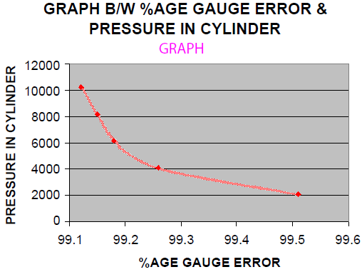
Then I plotted a graph between %age gauge error and pressure in cylinder.
|
S.No |
Piston mass |
Piston area |
Pressure in cylinder |
Gauge readings |
Absolute gauge error |
%Age gauge error |
|
1 |
0.5 |
244.8*10-6 |
2042.48 |
10 |
2032.48 |
99.51 |
|
2 |
1 |
244.8*10-6 |
4084.96 |
30 |
4054.96 |
99.26 |
|
3 |
1.5 |
244.8*10-6 |
6127.45 |
50 |
6077.45 |
99.18 |
|
4 |
2 |
244.8*10-6 |
8169.93 |
69 |
8100.93 |
99.15 |
|
5 |
2.5 |
244.8*10-6 |
10212.41 |
89 |
10123.41 |
99.12 |