Steel Structures used in Hydropower Projects

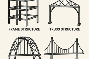
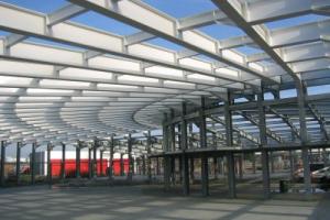
Steel structures play a crucial role in hydropower projects by providing necessary infrastructure for the efficient operation and management of the facilities. Following are some of the most common types of Steel Structures used in Hydropower Projects :
Steel Structures used in Hydropower Projects
- Trashracks
- Stoplogs
- Gates
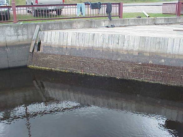
Trashracks
Trash racks are steel structures typically installed at the intake of a hydropower facility, such as a dam or a diversion channel. Their purpose is to prevent large debris, such as tree trunks, branches, and other floating objects, from entering the turbines or other sensitive equipment. Trashracks are designed with steel bars or mesh that allows water to pass through while trapping debris. This helps to protect the turbines from damage and maintain their performance efficiency. Trash racks and safety grates are critical elements of outlet structure design and serve several important functions. When properly designed, installed, and maintained trash racks.
- Keep debris away from the entrance to the outlet works where the debris will not clog the critical portions of the structure;
- Capture debris in such a way that relatively easy removal is possible;
- Ensure that people and large animals are kept out of confined conveyance and outlet areas; and, provide a safety system that prevents humans and animals from being drawn into the outlet and allows them to climb to safety.
Trash racks can serve these purposes without interfering significantly with the hydraulic capacity of the outlet (or inlet in the case of conveyance structures) (ASCE, 1985; Allred-Coonrod, 1991). The location and size of the trash rack depend on a number of factors, including head losses through the rack, structural convenience, safety, and size of the outlet
- Course/fine trashrack shall be designed for a design discharge of 1.27 m3/s at El: 2134.65 m and earthquake forces.
- The estimated trash rack bar size for the course trashrack shall be 20 mm and placed apart at 40 mm. The fine trashrack bar size shall be 20 mm.
- The rack bars will be manufactured from ASTM A36 material and epoxy painted against corrosion protection.
Stoplogs
Stoplogs are steel structures used to regulate water flow in a hydropower facility. They are generally large rectangular or cylindrical steel beams that can be inserted or removed vertically into slots or guides installed in dam structures. By inserting or removing these stoplogs, the water flow can be controlled or completely stopped, allowing for maintenance, inspections, or repairs of various components within the facility. Stoplogs are often used in spillway gates, diversion channels, and penstocks.
Stoplogs are hydraulic engineering control elements that are used in floodgates to adjust the water level and/or flow rate in a river, canal, or reservoir. Stoplogs are sometimes confused with flashboard, as both elements are used in bulkhead or crest gates. Stop logs are typically long rectangular timber beams or boards that are placed on top of each other and dropped into premade slots inside a weir, gate, or channel
Stoplogs are frequently used to temporarily block flow through a spillway or canal during routine maintenance. At other times, stoplogs can be used over longer periods, such as when a field is flooded and stop logs are being used in smaller gates to control the depth of water in fields. The logs may be left in and adjusted during the entire time that the field is submerged.
The stoplogs shall be designed and manufactured according to relevant DIN or ASTM standards considering the dead, hydrostatic, dynamic, friction, wind, and seismic loads.
Gates
Gates are steel structures used to control the flow of water in different parts of a hydropower facility. They can be used in various locations, such as spillways, penstocks, and turbine inlets. Steel gates are designed to be sturdy and watertight, allowing operators to adjust water flow rates, divert water to different channels or turbines, or completely close off water passages when needed. Gates can be operated manually, hydraulically, or electrically, depending on the specific project requirements.
- The stoplogs slots and sill will be of stainless steel.
- The gates shall be designed and manufactured according to relevant DIN or ASTM standards considering the dead, hydrostatic, dynamic, friction, wind, and seismic loads.
- The gates shall have a minimum 3/8" skin plate and are designed with a 2 mm wear/corrosion allowance.
- The gate wheels or rollers shall be spaced along the side of the gate disc to support an equal portion of the hydrostatic load. The wheels shall be turned treads and bored for proper bearing size. The wheel bearing shall be permanently lubricated and designed for continuous submergence service.
- Wire rope hoisting system is suggested for all the gates, however, the use of a hydraulic system shall also be studied during the detail design stage. The gates shall further be provided with lugs for emergency lifting, and maintenance locks in open position.
- Prefabricated structural steel slots will be provided.
- The bottom shall consist of a wide flange with stainless steel sealing surface.
- 'J' seals shall be mounted across the bottom and up both sides of the radial gate. Stainless steel plates shall be embedded across the invert and up both sides of the gate to provide a tight sealing in the closed position of the gate.
- The skin plate, stainless steel seal & other components of the gate shall be fabricated from relevant ASTM Standards such as ASTM A36, A242, ASTM A167, etc.
- Gates maintenance shall be performed in the dry season after first setting the stoplogs in front.