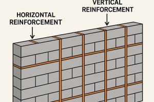
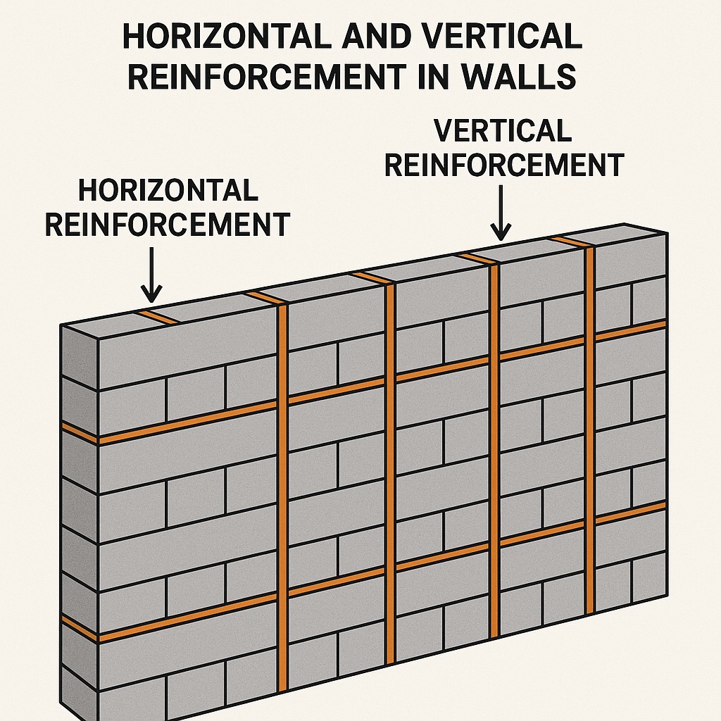
Horizontal and Vertical Reinforcement in Walls

Plan Requirements:
The designer (Architect/Engineer) of any project should indicate the following information on their plans:
- There should be separate cross-sections of all walls. Each cross section should clearly show the size of the block used (e.g., 4, 6, 8, or 10 inches) for the building inspector and installer.
- Each cross-section should show the wall heights involved for every storey.
- Vertical and horizontal reinforcing steel bar sizes, spacing, and steel grade should be marked for every storey in each wall cross-section or a separate note on other sheets.
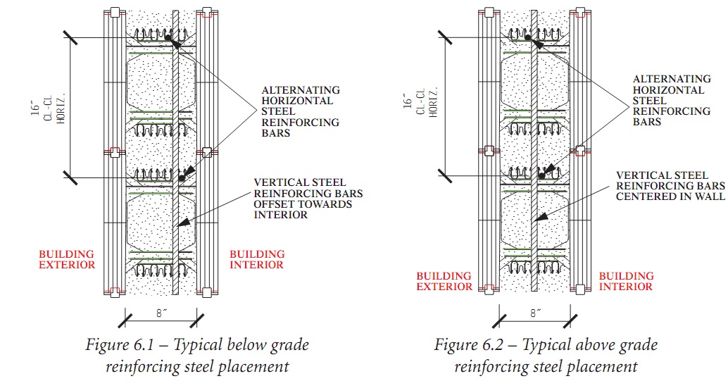
- The placement of reinforcing steel, especially the vertical ones, should be marked (i.e., off center or towards interior/exterior or centered in the wall). Also See: Bar Bending Schedule
- The designer should specify the lap splice type and lengths for every section of the wall where splicing is anticipated.
The Purpose of Reinforcing Bars:
Reinforced concrete structures are composed of two different materials
- Concrete
- Steel
Plain concrete is a strong material in compression. Compressing a plain concrete cube or cylinder requires a relatively large amount of compressive force before reaching compression failure. However, plain concrete is relatively weak in tension (typically can only carry one-tenth (1/10) of its compression strength in tension).
Reinforcing steel has excellent strength in both compression and tension loads, but is more expensive than concrete. Therefore, reinforced concrete structures are typically designed by engineers such that concrete is mainly utilized for most of the compressive forces and reinforcing steel is utilized for all of the tensile forces, and in some cases, some of the compressive forces. The design of reinforced concrete structures has been streamlined, particularly over the last century, for safety as well as economic feasibility. Reinforced concrete structures have had a tremendous track record in some of the most complicated structures, including dams, bridges, and high-rise buildings across the globe. Below is the placement of reinforcement in Shear Walls
Horizontal Reinforcement
Amvic polypropylene webs are specifically designed to accommodate and secure the horizontal reinforcing steel in place without the need to tie them. Typically, the first course of horizontal reinforcement is placed in the notches closer to the EPS panel. The second course of horizontal reinforcement is staggered so that it is placed in the notch towards the center of the concrete wall. The third course is placed in the same position as the first course. The fourth course is placed in the same position as the second. This staggered pattern of horizontal reinforcement is necessary to allow for the vertical reinforcement to be placed from the top and weave in between the horizontal steel bars below grade and above grade applications using 8" respectively.
Vertical Reinforcement
Vertical reinforcement is placed after the wall has been stacked and completely erected. In case of a multistory wall then the vertical reinforcement is placed after the erection of each storey. Vertical reinforcement bars are slid into place from the top and weaved into the horizontal reinforcement and secured into the proper place according to the project plans and specs.
Reinforcement for Wall Openings
Most walls will have window or door openings or both. Creating a wall opening in a reinforced concrete wall creates extra stress around that opening, especially at the corners. Window and door headers, also known as lintels, can be subjected to significant bending moments and shear forces depending on several factors.
Reinforcement Splicing
Steel reinforcement typically comes in 20-foot (6-meter) lengths. In such cases where steel reinforcement is required to exceed this length, a splice is required. The main purpose of the splice is to transform the stresses, whether tensile or compressive, from one steel reinforcing bar or a group of bundled bars to another in a manner to satisfy the governing local building/engineering codes and/or requirements of engineering plans and specs.
Types of Lap Splice
For the purpose and scope of this manual, we will only discuss one type of splicing, known as lap splicing. Lap splicing is typically overlapping reinforcing steel over a certain length. The length of the splice should be calculated according to the local building codes or by a local engineer and specified on the project plans.
There are two main types of lap splices:
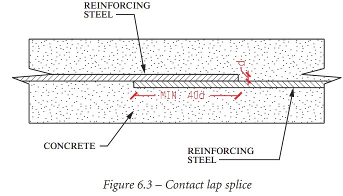
Contact Lap Splice
The lapped reinforcing bars MUST be in contact with each other and secured together.
Non Contact Lap Splice:
The reinforcing bars are allowed to be spaced at a distance of one-fifth (1/5) of the lapped length to a maximum of 150 mm or 6 inches.
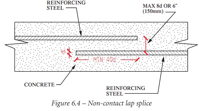
Minimum Requirement for Lap Splice Length
Both types of lap splices have a minimum splice length requirement as follows:
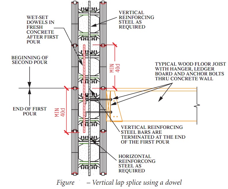
Lapped Splices for Multiple Concrete Pours
When a project has more than one storey of walls, it is necessary for the installer to understand how to perform vertical reinforcement lap splices between the different pours. There are two options, both of which are satisfactory from an engineering/structural standpoint.
Option 1
Extend the vertical reinforcement steel bars beyond the top level of the lower storey. The length of the extension should be equal to the required splice length specified by the design engineer or a minimum length of 40d (where d = diameter of smaller steel bar being spliced). Please refer to Figure 6.5 below for typical details.
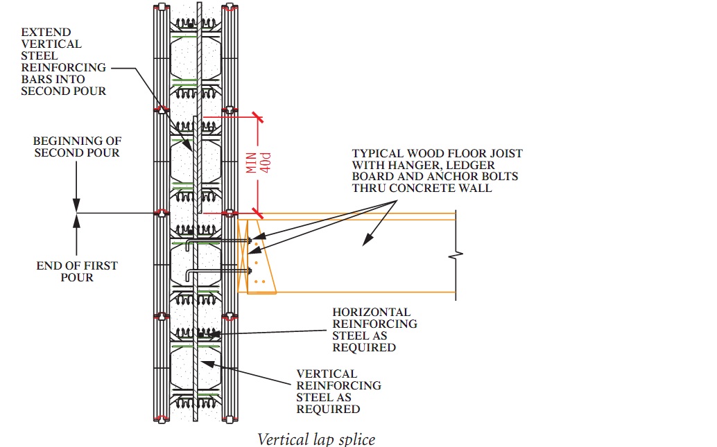
Example:
Canadian Reinforcing Steel System. When splicing a 10M reinforcing steel bar, which has a diameter of 11.3mm, the minimum lapped splice length is: 40 x 11.3mm = 452mm
Example:
US Reinforcing Steel System When splicing a #5 reinforcing steel ba,r which has a diameter of 0.625 inches, the minimum lapped splice length is: 40 x 0.625 inches = 25 inches
Option 2
Cut the vertical reinforcement steel bars for the lower storey so that they are flush with the top of that wall. Shortly after pouring the concrete, wet set additional vertical reinforcing bars, also known as dowel,s into the concrete. These should extend into the freshly poured wall a length equal to the splice length specified by the design engineer or a minimum length of 40d (where d = diameter of smaller steel bar being spliced). The wet-set vertical splice reinforcing steel bars should ALSO protrude into the upper wall by the same splice length specified by the design engineer or 40d as a minimum. Please refer to figure 6.6 below for details.
Designing Reinforcing Steel for Walls
Determining the reinforcing steel schedule, whether vertical or horizontal, is a structural engineering task that depends on many factors. This is beyond the scope of this technical manual, however, some tools are available for the residential construction market to assist in reinforcing steel design. The tools are explained below.
Canada:
CCMC report no.13043-R contains reinforcing steel tables for below-grade and up to 2 storeys of above-grade applications in residential projects. The report also contains some lintel tables for wall openings, both in metric and imperial units. There are applicability limits mentioned in the report that must be adhered to.
Code Requirements:
A - Design of reinforced concrete shall be in accordance with CSA A23.3.
B - Reinforcing steel placement shall conform to CSA A23.1, CSA A23.4, and/or the local building code having jurisdiction.
C - Reinforcing steel bars shall conform to clause 7 of CSA A23.1 AND CSA G30.18.
D - Minimum Steel Yield Strength shall not be less than 300 MPA (40 ksi).
United States:
NAHB (National Association of Home Builders) in association with PCA (Portland Cement Association) has prepared the "Prescriptive Method for Insulating Concrete Forms in Residential Construction" specifically for the ICF industry [REF. 1]. This document contains reinforcing steel schedules for grade and up to 2 storeys above grade applications. It also contains several lintel tables for wall openings in different applications. As expected, there are limitations that must be adhered to.
Code Requirements:
A - Design of reinforced concrete and placement of reinforcing steel bars shall be in accordance to ACI 318 or ACI 332 and/or the local building code having jurisdiction.
B - Reinforcing steel bars shall conform to one of the following specifications;
1 - ASTM A615 - Specifications for Deformed and Plain Billet-Steel Bars
B-2 - ASTM A706 - Specifications for Low-Alloy Steel Deformed and Plain Bars
B-3 - ASTM A996 - Specifications for Rail-Steel and Axle Steel Deformed Bars
C -Minimum yield strength of reinforcing steel shall be Grade 40 (300 MPa) except for seismic design categories D1 & D2, the minimum yield strength of reinforcing steel shall be Grade 60 (400 MPa).
For applications that fall outside the scope of the "Prescriptive Method," a local licensed/registered engineer should be retained. PCA (Portland Cement Association) has prepared another tool for engineers to assist in the design of ICF walls - "Structural Design of Insulating Concrete Form Walls in Residential Construction" [REF. 2]. This publication explains in more detail the engineering principles involved in designing load-bearing and non-load-bearing ICF wall,s even for walls outside the scope of "The Prescriptive Method".
Steel Reinforcing Bars and Jobsite Safety:
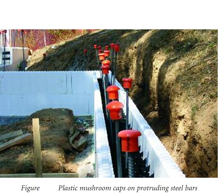
- Unguarded protruding steel reinforcing bars are hazardous and can result in injury or death. The following measures greatly reduce the hazards of exposed reinforcing steel:
- Guard all protruding ends of reinforcing steel bars with caps or wooden troughs, or
- Bend reinforcing steel so exposed ends are no longer upright.
- When employees are working at any height above exposed rebar, fall protection/ prevention is the first line of defense against impalement.
Code Compliance
According to OSHA (Occupational Safety & Health Administration - USA) article 1926.701 (b), the following clause shall apply to the job site: "All protruding reinforcing steel, onto and into which employees could fall, shall be guarded to eliminate the hazard of impalement." A similar compliance clause is present in OSHA (Occupational Health and Safety Act - Canada).