Surge Tanks, Function and Types of Surge Tanks
Surge Tanks Definition
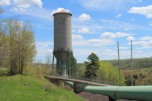
Surge tank (or surge chamber) is a device introduced within a hydropower water conveyance system having a rather long pressure conduit to absorb the excess pressure rise in case of a sudden valve closure. The surge tank is located between the almost horizontal or slightly inclined conduit and steeply sloping penstock and is designed as a chamber excavated in the mountain. There are three main types of surge tanks:
- Simple Surge Tank
- Restricted Surge Tank
- Differential Surge Tank
It also acts as a small storage from which water may be supplied in case of a sudden valve opening of the turbine. In case of a sudden opening of turbine valve, there are chances of penstock collapse due to a negative pressure generation, if there is no surge tank.
Surge Tank Function
When the valve in a hydroelectric power plant is suddenly completely closed, because of its small inertia the water in the penstock stops almost at once. The water in the pipeline, with large inertia retards slowly. The difference in flows between pipeline and penstock causes a rise in the water level in the surge tank. The water level rises above the static level of the reservoir water, producing a counter-pressure so that water in the pipeline flows towards the reservoir and the level of water in the surge tank drops. In the absence of damping, oscillation would continue indefinitely with the same amplitude.
The flow into the surge tank and water level in the tank at any time during the oscillation depends on the dimension of the pipeline and tank and on the type of valve movement. The main functions of a surge tank are:
- It reduces the amplitude of pressure fluctuations by reflecting the incoming pressure waves
- It improves the regulation characteristic of a hydraulic turbine.
The surge tank dimensions and location are based on the following considerations:
- The surge tank should be located as close to the power or pumping plant as possible;
- The surge tank should be of sufficient height to prevent overflow for all conditions of operation;
- The bottom of surge tank should be low enough that during its operation the tank is drained out and admit air into the turbine penstock or pumping discharge line; and
- The surge tank must have sufficient cross sectional area to ensure stability.
Types of Surge Tanks
There are different types of surge tanks that are possible to be installed. Some of the most common types of surge tanks which are as follows:
Simple Surge Tank:
A simple surge tank is a shaft connected to pressure tunnel directly or by a short connection of cross-sectional area not less than the area of the head race tunnel.
Restricted Orifice Surge Tank:
A type of surge tanks in which the inlet is throttled to improve damping of oscillations by offering greater resistance and connected to the head race tunnel with or without a connecting/communicating shaft
Differential Surge Tank:
Differential Surge tank is a throttled surge tank with an addition of a riser pipe may be inside the main shaft, connected to main shaft by orifice or ports. The riser may also be arranged on one side of throttled shaft.
In an underground development of hydropower system, tail race surge tanks are usually provided to protect tail race tunnel from water hammer effect due to fluctuation in load. These are located downstream of turbines which discharge into long tail race tunnels under pressure. The necessity of tail race surge tank may be eliminated by ensuring free-flow conditions in the tunnel but in case of long tunnels this may become uneconomical than a surge tank.
Water Surface Oscillation
The height of the surge tank is governed by the highest possible water level that can be expected during operation. Variations in demand initiated by a rapid opening or closure of the valve or turbine are followed with a time lag by the water masses moving in the tunnel. Upon the rapid and partial closure of the valve following a sudden load decrease, water masses in the penstock are suddenly decelerated, and one part of the continuous supply from the tunnel fills the surge tank. The water surface in the surge chamber will be raised to above static level.
In case of rapid opening, the flow in the tunnel is smaller than the turbine demand to supply water to the turbine. The water surface in the chamber will start to drop to below of the steady-state level. To establish steady-flow conditions, the water surface will again start to rise from the low point, but owing to the inertia of moving water, will again rise over the steady-level. The cycle is repeated all over again with amplitudes reduced by friction, i.e. the oscillation is damped. The phenomenon described is the water surface oscillation.


