What is Canal Head Regulators and Types of Canal Head Regulators


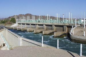
Canal Head Regulator
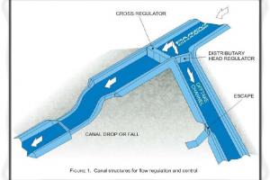
Structure at the head of canal taking off from a reservoir may consist of number of spans separated by piers and operated by gates. Regulators are normally aligned at 90° to the weir. Up to 10" are considered preferable for smooth entry into canal. The functions of canal head regulator are:
- To admit water into the off taking canal.
- To regulate the supplies into the canal.
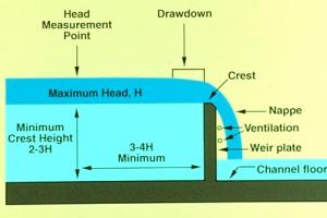
- To indicate the discharge passed into the canal from design discharge formula and observed head of water on the crest.
- To control the silt entry into the canal. During heavy floods, it should be closed otherwise high silt quantity will leave to the canal.
Types of Canal Head Regulator
Following are the common types of Canal Head Regulator:
- Still pond regulation:
- Open flow regulation
- Silt control devices
1. Still pond regulation:
- Canal draws water from still pond
- Water in excess of canal requirements is not allowed to escape under the sluice gates.
- Velocity of water in the pocket is very much reduced; silt is deposited in the pocket
- When the silt has a level about 1/2 to 1m below the crest level of Head Regulator, supply in the canal is shut off and sluice gates are opened to scour the deposited silt.
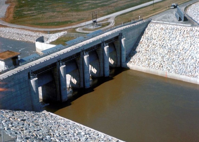
Head Regulator
2. Open flow regulation
- Sluice gates are opened and allow excess of the canal requirement
- Top water passes into the canal
- Bottom water maintain certain velocity in the pocket to keep the silt to remain in suspension
- Canal is not closed for scouring the silt.
3. Silt control devices
Another type of Canal Head Regulator is the silt control device
- Silt control at head works can be controlled by Providing a divide wall to Create a trap or pocket
- Create scouring capacity of under sluices By concentrating the currents towards them
- Paving the bottom the approach channel to reduce disturbance because due to disturbance sediment remains in suspension
Installing silt excluders
- Making entry of clear top water by Providing raised sill in the canal
- Lower sill level of scouring sluices
- Wide head regulator reduces velocity of water at intake
- Smooth entry to avoid unsteady flow
- Handling careful the regulation of weir
- Disturbance is kept at minimum in weirs
Silt excluder:
- Silt is excluded from water entering the canal, constructed in the bed infront of head regulator - excludes silt from water entering the canal
- Designed such that the top and bottom layers of flow are separated with the least possible disturbance
- Top water to canal - bottom, silt laden through under sluices
- No of tunnels resting on the floor of the pocket of different lengths
- The tunnel near th head regulator being of same length as that of the width of head regulator - tunnel of different length.
- Capacity of tunnel is about 20% of canal discharge
- Minimum velocity 2 to 3 m/s to avoid deposition in tunnel is kept the same as sill level of head regulator
- From discharge and scouring velocity the total waterway required for under water tunnels can be determined?
- Silt extractor or silt ejector:
- Device by which the silt, after it has entered the canal is extracted or thrown out.
- Constructed on the canal some distance away from head regulator
- Horizontal diaphragm above the canal bed
- Canal bed slightly depressed below the diaphragm 0.5 to 2.8m
- Under diaphragm, tunnel which extent the highly silted bottom water tunnel.
- There should be no disturbance of flow at the entry.
- Sediment - laden are diverted by curved vanes
- Forwards the escape chamber: steep slope to escape channel is provided.
- The streamlined vane passage accelerate the flow through them, thus avoiding deposition (decreasing section area increases the flow velocity)
- The tunnel discharge by gate at the outlet end (escape channel)
Location:
- If near head regulator, silt will be in suspension
- If too far away than result in silting of canal.