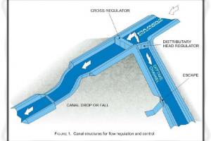
What is Barrage and What are the Basic Components of Barrage

Definition
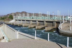
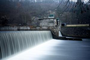
The only difference between a weir and a barrage is of gates, that is the flow in barrage is regulated by gates and that in weirs, by its crest height. Barrages are costlier than weirs.
Weirs and barrages are constructed mostly in plain areas. The heading up of water is affected by gates put across the river. The crest level in the barrage (top of solid obstruction) is kept at low level. During flood, gates are raised to clear of the high flood level. As a result there is less silting and provide better regulation and control than the weir.
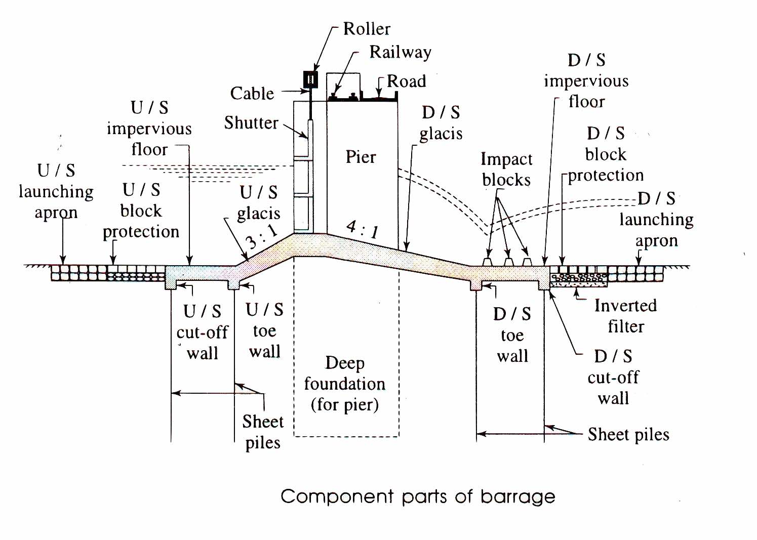
Components of Barrage
Shutters or Gates:
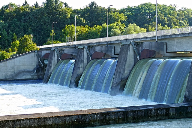
Weirs are provided either with shutters or counter balanced gates to maintain pond level. A shuttered weir is relatively cheaper but locks in speed. Better control is possible in a gated weir (barrage). Their function is:
- To maintain pond level.
- To raise the water level during low supplies. In case of higher floods, shutters are dropped down and overflow takes place while in case of gated weir, gates are raised during floods.
Main barrage portion:
- Main body of the barrage, normal RCC slab which supports the steel gate. In the X-Section it consists of :
- Upstream concrete floor, to lengthen the path of seepage and to project the middle portion where the pier, gates and bridge are located.
- A crest at the required height above the floor on which the gates rest in their closed position.
- Upstream glacis of suitable slope and shape. This joins the crest to the downstream floor level. The hydraulic jump forms on the glacis since it is more stable than on the horizontal floor, this reduces length of concrete work on downstream side.
- Downstream floor is built of concrete and is constructed so as to contain the hydraulic jump. Thus it takes care of turbulence which would otherwise cause erosion. It is also provided with friction blocks of suitable shape and at a distance determined through the hydraulic model experiment in order to increase friction and destroy the residual kinetic energy.
Divide Wall
It is a long wall constructed at right angle to the weir axis. It is extended up to the upstream end of the canal head regulator. In case of one canal off-taking from each bank of the river, one divide-wall is provided on front of each of the head regulators of the off takes. Similarly on the d/s side it should extend to cover the hydraulic hump and the resulting turbulence. The main functions are as follows:
- To generate a parallel flow and thereby avoid damage to the flexible protection area of the undersluice portion.
- To keep the cross-section, if any, away from the canal.
- To serve as a trap for coarser bed material.
- To serve as a side-wall of the fish ladder.
- To separate canal head regulator from main weir.
Fish Ladder
It is a narrow trough opening along the divide wall towards weir side provided with baffles (screen to control the flow of the liquid, sand etc.), so as to cut down the velocity of flowing water from u/s to d/s. location of fish ladder adjacent to divide wall is preferred because there is always some water in the river d/s of the under sluice only. It may be built within the divide wall. A fish ladder built along the divide wall is a device designed to allow the fish to negotiate the artificial barrier in either direction. In the fish ladder, the optimum velocity is (6-8) ft/sec.
This can be at Maralam Qadirabad & Chashma barrages. Fish move from u/s to d/s in search of relatively warm water in the beginning of water and return u/s for clear water before the onset of monsoon.
Sheet piles
Made of mild steel, each portion being 1.5' to 2' in width and 1/2" thick and of the required length, having groove to link with other sheet piles.
There are generally three or four sheet piles. From the functional point view, in a barrage, these are classified into three types:
- Upstream sheet piles
- Intermediate sheet piles
- Downstream sheet piles
1. Upstream Sheet Piles:
Upstream sheet piles are located at the U/S end of the U/S concrete floor. These piles are driven into the soil beyond the maximum possible scour that may occur. Their functions are:29. To protect the barrage structure from scour. 30. To reduce uplift pressure in the barrage floor. 31. To hold the sand compacted and densified between two sheet piles in order to increase the bearing capacity when the barrage floor is defined as raft.
Functions:
- Protect barrage structure from scour
- Reduce uplift pressure on barrage
- To hold the sand compacted and densified between two sheet piles in order to increase the bearing capacity when barrage floor is designed as raft.
2. Intermediate sheet piles:
- Situated at the end of upstream and downstream glacis. Protection to the main structure of barrage (pier carrying the gates, road bridge and the service bridge) in the event of the upstream and downstream sheet piles collapsing due to advancing scour or undermining. They also help lengthen the seepage path and reduce uplift pressure.
- Downstream sheet piles: Placed at the end of downstream concrete floor. Their main function is to check the exit gradient. Their depth should be greater than the possible scour.
3. Down Stream Piles:
- These are placed at the end of the d/s concrete floor and their main function is to check the exit gradient. Their depth should be greater than the maximum possible scour.
Inverted filter:
An inverted filter is provided between the d/s sheet piles and the flexible protection. It typically consists of 6” sand, 9’’ coarse sand and 9” gravel. The filter material may vary with the size of the particles forming river bed. It is protected by placing concrete blocks of sufficient weigh and size, over it.
Slits (jhiries) are left between the blocks to allow the water to escape. The length of the filter should be (2 × downstream depth of sheet pile). It performs following functions:
Functions:
- It checks the escape of fine soil particles in the seepage water.
- In the case of scour, it provides adequate cover for the downstream sheet piles against the steepening of exit gradient.
Flexible apron
A flexible apron is placed d/s of the filter of the filter and consists of boulders large enough not to be washed away by the highest likely water velocity. The protection is enough as to cover the slope of scour depth i.e. (112 × depth of scour on u/s side) and (2 × scour depth on the d/s side) at a slope of 31.
Under sluices: scouring sluices
Under sluice is the opening at low level in the part of barrage which is adjacent to the off takes. These openings are controlled by gates. They form the d/s end of the still ponds bounded on two sides of divide-wall and canal head regulator.
Functions:
They perform the following functions:
- To control silt entry into the canal.
- To protect d/s floor from hydraulic jump.
- To lower the highest flood level.
- To scour the silt deposits in the pockets periodically.
- To maintain a clear and well-defined river channel approaching the canal head-regulator. A number of bays at the extreme ends of the barrage adjacent to the canal regulator have a lower crest level than the rest of the bays. The main function is to draw water in low river flow conditions due to formation of a deep channel under sluice portion. This also helps to reduce the flow of silt into the canal due to drop in velocity of river water in deep channel in front of canal regulator. Accumulated silt can be washed away easily by opening the under sluice gates due to high velocity currents generated by lower crest levels or a high differential head.
- As the bed of under sluice is not lower level than rest of the weir, most of the day, whether flow unit will flow toward this pocket => easy diversion to channel through Head regulator
- Control silt entry into channel
- Scour the silt (silt excavated and removed)
- High velocity currents due to high differential head.
- Pass the low floods without dropping
- The shutter of the main weir, the raising of which entails good deal of labor and time.
- Capacity of under sluices:
- For sufficient scouring capacity, its discharging capacity should be at least double the canal discharge.
- Should be able to pass the dry weather flow and low flood, without dropping the weir shutter.
- Capable of discharging 10 to 15% of high flood discharge.