Sand Trap Design Criteria & Location for Construction

Definition:
Sand trap is a structure that is constructed to exclude the quantity of sand that is carried by water flowing in the channels or tunnels for power generation or irrigation or some other purposes. Sand trap is provided In the form of chambers that depends upon the discharge that is to be carried by the channel or tunnel.
As it is general and true believe the life of dam depends upon the rate and amount of silting to which it is subjected throughout it life time. Greater the rate of silting greater will be the amount of silt deposited which results in decrease in storage capacity of the dam or other hydraulic structure and decrease its service life. So to overcome this problem to some extent sand traps are provided that will try to reduce the amount of sand/silt in water and will allow almost sand free water to turbines in hydroelectric power generation plants. Apart form its good effect on service life of dams it has also a very positive effect on the service life of turbines. If the water that is to be used for power generation contains considerable amount of sand or silt, it will hit the turbines with greater impact and will cause erosion of turbine material and will try to decrease its life time as well.
Design of Sand Trap
Here in this example two cases of the sand trap will be solved that is
- Design of sand trap with two chambers
- Design of sand Trap with one camber
Design of sand trap is complicated step and a lot of parameters are to be considered during its design phase. Sand trap may be designed with or without top slab it depends on the situations if some traffic is to be passed over the sand trap then top slab is required to be constructed over the sand trap here in these examples we are not considering the top slab of the sand trap. The following is the criterion that is to be followed while designing a sand trap.
Design Criteria
- Particle Size (Assume)
- Flow Of Particle
- Sand Trap Dimensions
- Checks On Stand Trap Design
Design Example
(Sand Trap with two chambers)
The following is a practical example of designing a sand trap.
Design a Sand Trap for the following conditions.
BASIC DATA
DESIGN DISCHARGE Q = 4.5 m3/s
NO OF CHAMBERS N = 2 No
DISCHARGE/CHAMBER Q/N = 2.25 m3/s
PARTICALE SIZE d = 0.2 mm
SP. WT OF PARTCLE lS = 2.7 Ton/m3
SP. WT OF FLUID lF = 1 Ton/m3
DYNAMIC VISCOSITY μ = 0.0009 N-s/m2
APPROACH CHANNEL WIDTH B' = 2.5 m
FLOW VELOCITY
Flow velocity in the sand trap Vd = 0.20 m/s
Coefficient as a function of d a = 44.00
Settling velocity of sand in flowing water ω = 0.20 m/s
Settling velocity of sand in standing water ω0 = 0.21 m/s
Critical mean flow velocity Vmc = 0.20 m/s
DIMENSIONS
1. LENGTH
Effective settling length of Sand Trap L = 42.50 m
Effective settling length (Provided) L (Provided)= 45 m
Settling depth H = 4 m
Settling velocity in standing water Vs' = 0.0264 m/s
Settling velocity in flowing water Vs = 0.0134 m/s
Reduction Factor a = 0.0660
2. WIDTH
Width of Chamber B = 2.85860963 m
Width of Chamber (Provided) B (Provided) = 3m
Time of passage td = 228.6887 s
Round the width of the sand trap to nearest whole number and that width will be used in the design of sand trap
3. DEPTH
Depth of Sand Trap H = 4m
Any value up to 1.5B can be assumed for the sand trap depth.
4. TRANSITION LENGTH
Transition length of Sand Trap T.L = 6.528337164 m
Transition length (provided) T.L (Provided) = 6.55 m
Total width of Sand Trap Bt = 6 m
Approach Channel width B' = 2.5 m
Angle of Transition length with horizontal ? = 15 Degree
Transition length should be also round to nearest 1/25 number so that it can be layout easily in the field. Transition angle is the angle that the sloped side of the sand trap at its start makes with the wall of sand trap and is nearly kept in the range of 13-16 Degrees.
B' is the width of the approaching channel towards the sand trap and is needed to be determined before the designing of the sand trap.
Following are the few checks that are needed to applied on the designed dimensions of the sand trap in order to check its adequacy with the design standards.
CHECKS ON DIMENSIONS
1. LENGTH Vmc x H/Vd
CHECK L ≥ Vmc x H/Vd OK
CHECK L ≥ B x 8 OK
2. WIDTH Q / (Vmc x H)
CHECK B= Q / (Vmc x H) OK
CHECK L/8 ≥ B OK
CHECK B ≤ H / 1.25 OK
3. TRANSITION LENGTH
CHECK T.L ≤ L /3 OK
CHECKS ON VELOCITY
VELOCITY
Roughness Coefficient (Concrete) 0.015
66.66666667
Vcr = 0.232272283
CHECK Vcr ≥ Vd OK
Slope of sedimentation tank = 0.03
Effective depth of chamber at end = 5.35
Mean Area of Chamber = 14.025
Mean velocity in chamber = 0.160427807
CHECK Vcr ≥ Vm OK
FINAL DIMENSIONS
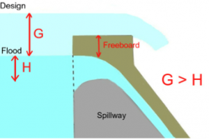
Freeboard in sandtrap (assumed) f.b. = 0.5 m
Thickness of top slab (assumed) tt = 0.3 m
Width of side walls (assumed) wsw = 0.5 m
Thickness of bottom slab (assumed) tb = 0.6 m
Width & height of flushing canal (assumed) Wfc = 0.6 m
Total height of chamber (at start) HTS = 6.9 m
Total height at deepest point (at end) HTE = 8.55 m
So summarizing all the above results and calculations the finalized dimensions of Sand Trap for the given data are.
LENGTH OF SAND TRAPE L (Provided) = 45 m
WIDTH of single chamber (internal) B (Provided) = 3 m
THICKNESS OF CHAMBER WALL (assume) b = 0.5 m
TOTAL WIDTH OF SAND TRAP (external) Bt = 7.5 m
DEPTH OF SAND TRAP H = 4 m
TRANSITION LENGTH OF SAND TRAP T.L (Provided) = 6.55 m
TRANSITION ANGLE ? = 15 Degree
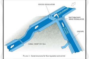
LOCATION FOR SAND TRAP CONSTRUCTION
After getting the dimensions of the sand trap the next step is the construction of sand trap. The location for sand trap construction is governed by the following factors.
- The location of sand trap should not be to closed to the Main channel or River because heavy rains or flood may cause the sand trap to be over flooded.
- It should be constructed in alignment with the Headrace channel to allow the smooth transition of water in to sand trap.
- Maximum effort should be made to construct sand trap in cut in order to increase its life time and stability in the long terms. Construction of sand trap in fill can cause serious problems such as, Failure due to sliding, differential settlement, bed erosion etc.
REMOVAL OF SAND FROM SAND TRAP
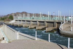
Sand that is collected in the sand trap can be removed from the sand trap using flushing pipe provided at the side walls of the sand trap near its bottom as shown in the picture.
The flushing pipe must be provided in such a place so that it can be easily operated and the deposited sand can be flush out in to near by channel or some water course and needs to be operated and cleaned on regular basis.
DESIGN EXAMPLE
(Sand Trap with One chambers)
In this case only one chamber is assumed in the sand trap. The selection of number of chambers depends upon the given discharge and some times on the topography of the area is well. The rest of the design is same as that of the sand trap with two chambers.
The following is a practical example of designing a sand trap.
Design a Sand Trap for the following conditions.
BASIC DATA
DESIGN DISCHARGE Q = 3 m3/s
NO OF CHAMBERS N = 1 No
DISCHARGE/CHAMBER Q/N = 3 m3/s
PARTICLE SIZE d = 0.2 mm
SP. WT OF PARTCLE lS = 2.7 Ton/m3
SP. WT OF FLUID lF = 1 Ton/m3
DYNAMIC VISCOSITY μ = 0.0009 N-s/m2
APPROACH CHANNEL WIDTH B' = 2.5 m
FLOW VELOCITY
Flow velocity in the sand trap Vd = 0.20 m/s
Coefficient as a function of d a = 44.00
Settling velocity of sand in flowing water ω = 0.20 m/s
Settling velocity of sand in standing water ω0 = 0.21 m/s
Critical mean flow velocity Vmc = 0.20 m/s
DIMENSIONS
1 LENGTH
Effective settling length of Sand Trap L = 47.82 m
Effective settling length (Provided) L (Provided)= 50 m
Settling depth H = 4.5 m
Settling velocity in standing water Vs' = 0.0264 m/s
Settling velocity in flowing water Vs = 0.0141 m/s
Reduction Factor a = 0.0622
2 WIDTH
Width of Chamber B = 3.387981784 m
Width of Chamber (Provided) B (Provided) = 3.5 m
Time of passage td = 254.0986338 s
3 DEPTH
Depth of Sand Trap H = 4.5 m
4 TRANSITION LENGTH
Transition length of Sand Trap T.L = 1.86523919 m
Transition length (provided) T.L (Provided) = 1.9 m
Total width of Sand Trap Bt = 3.5 m
Approach Channel width B' = 2.5 m
Angle of Transition length with horizontal ? = 15 Degree
CHECKS ON DIMENSIONS
1 LENGTH Vmc x H/Vd
CHECK L ≥ Vmc x H/Vd OK
CHECK L ≥ B x 8 OK
2 WIDTH Q / (Vmc x H)
CHECK B= Q / (Vmc x H) OK
CHECK L/8 ≥ B OK
CHECK B ≤ H / 1.25 OK
3 TRANSITION LENGTH
CHECK T.L ≤ L /3 OK
CHECKS ON VELOCITY
VELOCITY
Roughness Coefficient (Concrete) 0.015
66.66666667
Vcr = 0.268274486
CHECK Vcr ≥ Vd OK
Slope of sedimentation tank = 0.03
Effective depth of chamber at end = 6
Mean Area of Chamber = 18.375
Mean velocity in chamber = 0.163265306
CHECK Vcr ≥ Vm OK
FINAL DIMENSIONS
Freeboard in sandtrap (assumed) f.b. = 0.5 m
Thickness of top slab (assumed) tt = 0.3 m
Width of side walls (assumed) wsw = 0.5 m
Thickness of bottom slab (assumed) tb = 0.6 m
Width & height of flushing canal (assumed) Wfc = 0.6 m
Total height of chamber (at start) HTS = 7.65 m
Total height at deepest point (at end) HTE = 9.45 m
Where fb is the free board i.e the distance from water top surface to the top level of the sand trap wall/edge.
LENGTH OF SAND TRAPE L (Provided)= 50 m
WIDTH of single chamber (internal) B (Provided)= 3.5 m
THICKNESS OF CHAMBER WALL (assume) b = 0.5 m
TOTAL WIDTH OF SAND TRAP (external) Bt = 4.5 m
DEPTH OF SAND TRAP H = 4.5 m
TRANSITION LENGTH OF SAND TRAP T.L (Provided) = 1.9 m
TRANSITION ANGLE ? = 15 Degree