Levelling Tools & Equipment
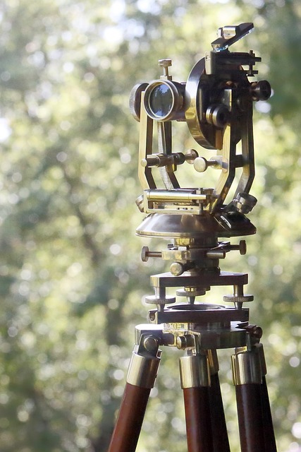
The vertical measuring equipment in surveying is major summed into two but other instruments still exist. The two major Levelling Equipment are:
-
Measurement by surveying levels
-
Barometric – pressure devices
These two major groups of instruments are exclusively used for determining vertical (as well as horizontal) levels or elevations.
Surveying Levels:
There are four types of surveying levels:
- The wye, or the dumpy level (see Fig. 10 & 11)
- The tilting level,
- the self–leveling level; and
- Digital electronic level
Dumpy Level:
The first type consists of a telescopic sight. Like that of a transit but usually of slightly higher magnification, to which a long spirit level (see Fig. 11) is attached and adjusted so that the bubble centers when the line of sight is horizontal. 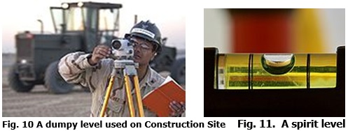 A dumpy level is also known as a builder’s auto level, leveling instrument, or automatic level. It is an optical instrument used in surveying and building to transfer measures or set horizontal levels.
The level instrument is set up on a tripod and, depending on the type, either roughly or accurately set on a leveled condition using foot screws (Leveling screws). The operator looks through the eyepiece of the telescope while as assistant holds a tape measure or graduated staff vertically at the point under measurement. The instrument and staff are used to gather and/or transfer elevation (levels) during site surveys. Measurement generally starts from the benchmark with a known height determined by a previous survey, or an arbitrary point with an assumed height. A dumpy level (Fig 10) is an older-style instrument that requires skilled use to set accurately. The instrument requires to be set level in each quadrant to ensure it is accurate through a full 360o traverse.
A variation in the dumpy and one that was often used by surveyors, where greater accuracy and error checking was required, is a tilting level. This instrument allows the telescope to be effectively flipped through 180o, without rotating the head. The telescope is hinged to one side of the instrument’s axis; flipping it involves lifting it to the other side of the central axis (thereby inverting the telescope). This action effectively cancels out any errors introduced by poor setting procedures or errors in the instrument’s adjustment. The tilting level is similar to dumpy but the telescope with the main bubble attached can be separately tilted up and down by means of a micrometer screw, giving it greater accuracy.
Self Level:
The self-leveling level is similar to the tilting level except that it has no micrometer screw. Instead, self –leveling level contains an internal compensator mechanism (a swinging prism or pendulum) that, when set close to the level, automatically removes any remaining variation from the level. This automatically reduces the need for setting the instrument for leveling as in the case of dumpy and tilting levels. Self-leveling instruments are a highly preferred instrument in surveying due to their ease of use and minimal rapid set up time-consuming.
Digital Level:
A digital electronic level is another leveling instrument set up normally on a tripod and it reads a bar–coded staff using electronic laser methods. The height of the staff where the level beam crosses the staff is known on a digital display. This type of level removes interpolation of graduation by a person, thus removing a source of error and increasing accuracy.
The level rod or level Staff:
A level staff, also called leveling rod, is a graduated wooden or aluminum rod, the use of which permits the determination of differences in metric graduation as the left and imperial on the right (see Fig. 12) leveling rods can be one piece, but many are sectional and can be shortened for storage and transport or lengthened for use. Aluminum rods may adjust the length by telescoping sections inside each other, while wooden rod sections are attached to each other with sliding connections or slip joints. There are many types of rods, with names that identify the form of the graduations and other characteristics. Marking can be in imperial or metric units. Some rods are graduated on only one side while others are marked on both sides. If marked on both sides, the markings can be identical or, in some cases, can have imperial units on one side and metric on the other side.
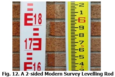
Fig. 12. A 2-sided Modern Survey Levelling Rod
Pressure Measuring Surveying Devices
Aneroid Barometers:
Vertical measurements can be approximately determined by finding the difference in barometric pressure at the two elevations. Aneroid barometers and hypsometers measure such differences. Aneroid barometers are devices in which changes in atmospheric pressure cause a needle to move over a scale. Instruments of this type designed for surveying are called altimeters. A type that records time along with pressures is usually placed at the points where measurements of elevation are desired. When the second instrument is read, the time is recorded, so that the simultaneous reading of the base instrument can be selected (see Fig. 14 (a) and 14 (b)). The difference between the two readings must be corrected to the unit weight of the air, which is estimated from the barometric pressure, temperature, and humidity.
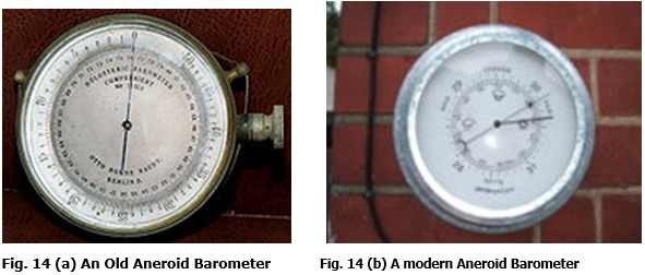
Fig. 14 (a) An Old Aneroid Barometer Fig. 14 (b) A modern Aneroid Barometer
More accurate results are independent of the unit weight of the air can be obtained by the two–base method. Recording aneroids are placed at two bases, preferably one higher and another lower than the elevations to be determined. Each field reading is adjusted in proportion to the relative height above and below the two bases so that the sum of the two heights equals the known difference in the height between the bases. Within a radius of ten miles (16 kilometers) this method gives elevations within about two feet 0.6 meters).
Hypsometers:

A hypsometer is an instrument for measuring height or altitude. Many different physical principles may be used. A simple scale hypsometer allows the height of a building or tree to be measured by sighting across a ruler to the base and top of the object being measured when the distance from the object to the observer is known. A pressure hypsometer (as shown in Fig. 15) employs the principles that the boiling point of the liquid is lowered by diminishing the barometric pressure, and that the barometric pressure varies with the height of the point of observation. The instrument consists of a cylindrical vessel in which the liquid, (usually water) is boiled and surmounted by a jacketed column in the outer partitions of which the vapor circulates, while in the central one, a thermometer is placed. To deduce the height of the station from the observed boiling point, it is necessary to know the relationship existing between the boiling point and pressure, and also between postmasters use the combination of a laser range finder and a clinometer to measure distances to the top and bottom of objects, and the angle between the lines from the observer to each to calculate height.
Fig. 15. Hypsometer
Plane table:
This shows a plane table with part of the surface of the table cut away to show the mounting of the tripod. The mount allows the table to be leveled on the table; the alidade with telescope sight is seen in Fig 16. A plane table consists of a smooth table surface mounted on a sturdy base. The connection between the tabletop permits one to level the table precisely, using bubble levels, in a horizontal plane. The base, a tripod, is designed to support the table over a specific point on land. By adjusting the length of the legs, one can bring the table level regardless of the roughness of the terrain
Usably, a plane table is set over a point and brought to a precise horizontal level. A drawing sheet is attached to the surface and an alidade is used to sight objects of interest. The alidade, which is a modern example of an instrument, “a rule” with a telescopic sight can then be used to construct a line on the drawing that is in the direction of the object of interest. By using the alidade as a surveying level, information on the topography of the site can be directly recorded on the drawing as elevations. Distances to the objects can be measured directly or by the use of stadia marks in the telescope of the alidade.
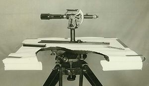
Fig. 13. A Plane Table


